Test System Design
Design principles and processes help the engineer solve challenging open ended problems. If a proper process is followed the engineer can be confident that their solution is defensible, and likely to work when implemented.
In school design is often illustrated as a variant of a cyclical process that involves Defining the problem, research, brainstorming ideas, and designing a solution. Once a design (model / drawing / schematic) is prepared the Build-Test-Evaluate loop begins. The number of iterations of the Build-Test-Evaluate loop depends on how many checks the customer wants to write 😃

In test system development the outcome of “defining the problem” is a system block diagram. What is a system?
A system is a group of interacting or interrelated elements that act according to a set of rules to form a unified whole. A system, surrounded and influenced by its environment, is described by its boundaries, structure and purpose and expressed in its functioning.
A Test System is a software controlled electromechanical system. Designing a test system requires a multi-disciplinary team. The design process described in this post is a universal process that can be used in any discipline.
Rule #1: Create a system block diagram.
A system block diagram enables visualization of a system as a set of interacting, decoupled components. The components can be replaced with other similar components without affecting the purpose or function of the system. A sample block diagram is shown below. The lines between various blocks typically show the flow of signal/data.

The block diagram above might seem overly simplistic. What test system could it possibly represent? It could represent a simple battery tester. A computer is connected to a DAQ/DMM and the fixture is a simple battery holder with 2 wires going to the DAQ which measures voltage.
However simple this might seem, it is the basis for testing battery cells on high speed assembly lines. However instead of one, an industrial battery tester will use a bed of nails to test 48 batteries at a time. A multiplexer (MUX) would be used to switch the DMM between individual batteries to perform 48 measurements.
The fixture shown in the block diagram above is a sub-system and would have its own block diagram showing its internal design. Each block in the block diagram would be a part or sub-assembly in the Bill Of Materials (BOM) of the test system.
The system block diagram is a design tool used to show the interconnections between decoupled subsystems and components which can be specified independently of other components in the system. Use the block diagram to evaluate and modify the old / reference design to suit the new requirements.
Rule #2: Gather the test and system requirements.
After creating a system block diagram, the next task is to specify the system requirements. System requirements and constraints are in the form of:
- power requirements (AC/DC, voltage, current, power)
- space requirements (size of control cabinet/rack, distance between instrumentation and controller)
- Device Under Test (DUT) and test fixture requirements (size, shape, number of required measurements)
- environmental constraints (noise, dust, temperature, humidity, splash/spill protection)
The four requirements above are hardware requirements. There are also test sequence / software requirements. These are specified by the customer and they describe the test procedure or test algorithm. This typically includes the stimulus to be applied to the DUT (voltage, pressure etc.), and the range of the expected response. The applied stimulus is typically user configurable and is called test parameter / configuration, and the expected response is called the test limit.
Rule #3: Copy a reference design as a starting point.
The block diagram and requirements provide a rough outline of the desired solution. The next step is to design the sub-systems, and specify the components and interconnections. A lot of engineering is “copy-paste”. It means copying old designs and tweaking it to fit the new application. This is not only pragmatic, but also necessary.

In industry learning from your mistakes is expensive. The goal in industry isn’t to invent a novel solution to every problem. It’s about deploying proven, robust solutions quickly, and creating value. So go through old designs and start with something that has been proven to work. If you work at a start-up or you work in a newly created department with no history, then look at sample/reference designs described in user manuals and datasheets of instruments. Talk to the applications engineering departments of large equipment vendors in your industry. Even local distributors of test instruments have technical sales and applications engineering teams that are happy to help you design a solution.
Rule #4: Thoroughly analyze components along different dimensions before selecting them for the design.
The system requirements and constraints limit the solution space, and the block diagram provides a rough outline of the required solution but they do not specify the design implementation. There is plenty of room for creativity. A block diagram isn’t a design, it’s a description of the design.
Design begins with component selection. Component selection is a collaborative effort of a multi-disciplinary team. A component’s properties can be grouped into mechanical, electrical and software categories. The selected component must meet the requirements of each discipline.
Component selection is a balancing act. RPG players are familiar with the concept that you cannot maximize all the stats on your character. You have to make choices and accept trade-offs.
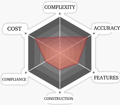
System components should be evaluated for suitability along the following dimensions:
Cost: Purchase, calibration, maintenance (spare parts, accessories), software/licensing, and operator training.
Complexity: Difficulty of setup, installation, and control system interface. Also related to properties such as modularity, extensibility, and inter-changeability which are aspects of flexibility. Highly flexible systems have higher complexity.
Compliance: Compliance with safety or quality standards such as CE, UL, ETL, CSA, ATEX (explosion) and IP (ingress protection).
Construction: Refers to the mechanical (size, shape, material) and electrical properties (voltage, current, digital interface) of the component. Also includes operating limits (environmental parameters such as temperature, pressure etc.) and failure conditions (burst pressure, overvoltage etc.).
Accuracy: Refers to accuracy, precision, resolution, linearity, and other performance metrics.
Features: Depending on the component being considered features are the key differentiators for components that are otherwise equivalent in all other dimensions. Includes hardware and software features. In industrial automation software features are more valuable since physical interaction with the component will be a rare occurrence.
The components can be assigned a score out of 10 where higher scores are assigned for desired characteristics (low cost, low complexity, high accuracy etc.). The relative strengths of various options can then visualized on the radar chart.
If starting from a reference design use the system block diagram as a filter to remove all unnecessary components, and identify components that could present compatibility issues with new components that are expected to be included in the design. Then start selecting critical components — components that have the biggest impact on the performance of the test system. This is usually the data acquisition system, control system, and instrumentation. Design the rest of the system around the selected critical components.
Rule #5: Vet the design through design reviews. Create prototypes, and perform proof of concept studies whenever possible.
The test system design is now nearing completion. The final step is analysis and review. Will the design work? Based on the complexity of the project and the risks involved this can be determined through:
- a review of design features, assumptions, and calculations against design and test requirements, and constraints
- review of applicable EHS (environment, health, safety) standards
- simulation: Finite element analysis (FEA), thermal analysis, circuit simulation and other techniques
- proof of concept (POC) / proof of principle (POP) studies to ensure that the chosen test method / instrument will meet the test requirements
- analytic processes such as Design failure mode and effects analysis (DFMEA)
The purpose of these reviews and studies is to ensure that the design meets the requirements and doesn’t have any obvious flaws or issues. System behavior and functionality is emergent, i.e. “you don’t know until you try”. No amount of simulation, prototyping or POP studies can guarantee that the design is ultimately successful when the system is built and integrated. However a design that has been rigorously reviewed is well understood so there will be fewer issues that occur, and any issues that arise can be resolved in less time since the design team has a deep understanding of the system requirements, design criteria and design intent and will know the right things to modify or tweak to resolve the issues.
Finally, if you want to be a good test engineer, commit this quote to memory:
One good test is worth a thousand expert opinions